IA-32
and x86-64 The
two massively popular architectures IA-32 and x86-84 are so common that they are described in a single set of manuals
.
The following notes briefly summarize the latter architecture only.
x86-64 Architecture Diagram The basic
architecture of the x86-64
is described in Volume 1 of the System Developer’s Guide. The following diagram is taken directly from Chapter 3 of this volume:
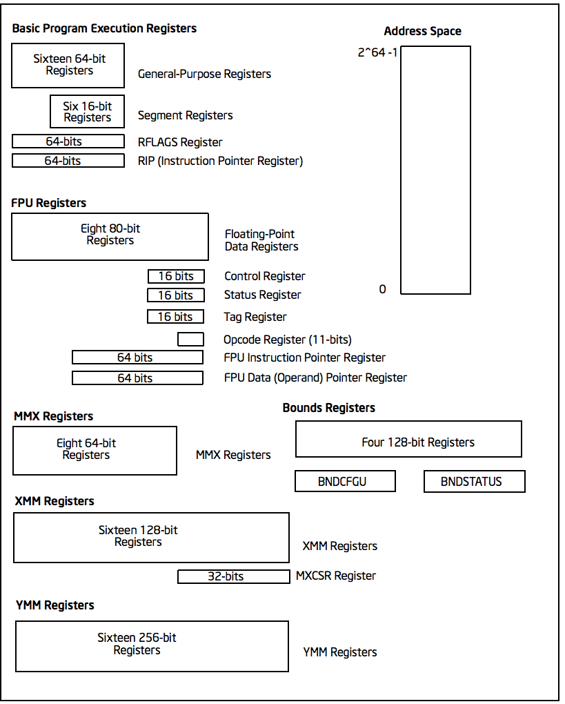
Records Application
programmers generally use only general-purpose registers, floating-point registers, XMM registers, and YMM
registers.
General
purpose registers These are 64 bits wide and are used for integer arithmetic and logic, and to keep data and pointers in memory. The records are called R0… R15. Also:
- You can access the lower 32-bit order of each register using the R0D names… R15D. The “D” stands for “double word” because strangely, the word “word” on this platform refers to a number of 16 bits. Why? Backward compatibility! The x86-64 grew out of a family of 16-bit processors created in the 1970s.
- You can access the 16 lower-order bits of each register using the names R0W… R15W.
- You can access the 8 lower-order bits of each register using the names R0B… R15B.
- A0… R7 have aliases RAX, RCX, RBX, RDX, RSP, RBP, RSI, RDI, respectively.
- R0D… R7D has aliases EAX, ECX, EBX, EDX, ESP, EBP, ESI, EDI, respectively.
- R0W… R7W have aliases AX, CX, BX, DX, SP, BP, SI, DI, respectively.
- R0B… R7B has aliases AL, CL, BL, DL, SPL, BPL, SIL, DIL, respectively.
RIP and RFLAGS RIP
is
the instruction pointer and RFAGS is the flag register
.
Segment registers
These are CS, DS, SS, ES, FS and GS. I haven’t used them in 64-bit programming.
XMM registers
These are 128 bits wide. They are called XMM0… XMM15. Use them for floating-point arithmetic and integers. You can perform operations on 128-bit integers, but you can also take advantage of its ability to perform
operations in parallel: Two 64-bit integer operations in parallel Four 32-bit integer operations in parallel Eight 16-bit integer operations in parallel Sixteen 8-bit integer operations in parallel Two 64-bit floating-point operations in
- Four 32-bit
- in
parallel
floating-point operations
Parallel YMM registers
These are 256 bits wide. They are called YMM0… YMM15. Use them for floating-point arithmetic. It can do:
Four 64-bit floating-point operations in parallel Eight 32-bit floating-point operations in parallel
and a few other crazy things
.
FPU Registers
There are eight registers used to calculate with 80-bit
- floating-point
values. Records do not have names because they are used in stack form.
Other
registers Application programmers can remain oblivious to the rest of the
registers:
- The 8 control registers of the 32-bit processor: CR0, CR1, CR2, CR3, CR4, CR5, CR6, CR7. The bottom 16 bits of CR0 are called machine status word (MSW).
- 4 16-bit tables record: GDTR, IDTR, LDTR and TR
- 5 test records: TR3, TR4, TR5, TR6 and TR7. The
- range of memory types
- registers
- ,
The
. The 8 32-bit debug registers: DR0, DR1, DR2, DR3, DR4, DR5, DR6 and DR7. The
records machine-specific
Machine check records instruction set See Volume 1
SDM Chapter 5 for a good overview of
all processor instructions and Volume 2 for complete information
. The following table lists most of the
available statements, using the instruction names specified in Intel syntax. Not all processors support all instructions, of course.
The vertical bar means OR, the brackets mean OPTIONAL, and the parentheses are used for grouping. For example:
- SH(L|R)[D] stands for SHL, SHR, SHLD, SHRD.
- A[D]] stands for PUSH, PUSHA, PUSHAD.
PUSH[
INTEGER FPU SSE SSE2 MOV CMOV[N]((L|G| A| B)[E]| E| Z| S| C|O| P) XCHG BSWAP XADD CMPXCHG[8B] PUSH[A[D]] | POP[A[D]] EN | OUT CBW | CWDE | CWD | MOVSX CDQ | MOVZX ADD | ADC SUB | SBB [I]MUL [I]DIV INC | DEC NEG CMP DAA | DAS AAA | AAS | AAM | AAD AND | OR | XOR | NO SH(L|R)[D] SA(L|R) RO(L|R) RC(L|R) BT[S| R| C] BS(F| R) SET[N]((L|G| A| B)[E]| E| Z| S| C|O| P) PRUEBA JMP J[N]((L|G| A| B)[E]| E| Z| S| C|O| P) LOOP J[E]CXZ[N][Z| E] CALL | RET INT[O] | IRET ENTER | LEAVE MOVS TIED[B| W| D] CMPS[B| W| D] SCAS[B| W| D] LODS[B| W| D] STOS[B| W| D] INS[B| W| D] OUTS[B| W| D] REP[N][Z| E] STC | CLC | CMC ETS | CLD ITS | CLI LAHF | SAHF PUSHF[D] | POPF[D] LDS | LES | EPA | LGS | LSS LEA NOP UD2 XLAT[B] CPUID F[I]LD F[I]ST[P] FBLD FBSTP FXCH FCMOV[N](E| B|BE| U) FADD[P] FIADD FSUB[R][P] FISUB[R] FMUL[P] FIMUL FDIV[R][P] FIDIV[R] FPREM[1] FABS FCHS FRNDINT FSCALE FSQRT FXTRACT F[U]COM[P][P] FICOM[P] F[U]COMI[P] FTST FXAM FSIN FCOS FSINCOS FPTAN FPATAN F2XM1 FYL2X FYL2XP1 FLD1 FLDZ FLDPI FLDL2E FLDLN2 FLDL2T FLDLG2 FINCSTP FDECSTP FFREE F[N]INIT F[N]CLEX F[N]STCW FLDCW F[N]STENV FLDENV F[N]SAVE FRSTOR F[ N]STSW FWAIT | WAIT FNOP FXSAVE FXRSTOR MOV(A| U)PS MOV(H| HL| L|LH)PS MOVSS MOVMSKPS ADD(P| S)S SUB(P| S)S MUL(P| S)S DIV(P| S)S RCP(P| S)S SQRT(P| S)S RSQRT(P| S)S MAX(P| S)S MIN(P| S)S CMP(P| S)S [U]COMISS ANDPS ANDNPS ORPS XORPS SHUFPS UNPCK(H| L)PS CVTPI2PS CVT[T]PS2PI CVTSI2SS CVT[T]SS2SI PAVG(B| W) PEXTRW PINSRW P(MIN| MAX)(UB|SW) PMOVMSKB PMULHUW PSADBW PSHUFW LDMXCSR STMXCSR MASKMOVQ MOVNT(Q|PS) PREFETCHT(0|1|2) PREFETCHNTA SFENCE MOV(A| U)PD MOV(H| L)PD MOVSD MOVMSKPD ADD(P| S)D SUB(P| S)D MUL(P| S)D DIV(P| S)D SQRT(P| S)D MAX(P| S)D MIN(P| S)D CMP(P| S)D [U]COMISD ANDPD ANDNPD ORPD XORPD SHUFPD UNPCK(H| L)PD CVT(PI| DQ)2PD CVT[T]PD2(PI| DQ) CVTSI2SD CVT[T]SD2SI CVTPS2PD CVTPD2PS CVTDQ2PS CVT[T]PS2DQ CVTSS2SD CVTSD2SS MOVDQ(A| U) MOVQ2DQ MOVDQ2Q PUNPCK(H| L)QDQ PADDQ PSUBQ PMULUDQ PSHUF(LW| HW| D) PS(L|R)LDQ MASKMOVDQU MOVNT(PD| DQ| I) CLFLUSH LFENCE MFENCE PAUSE SYSTEM MMX SSE3 SSE4 LGDT | SGDT LLDT | SLDT LTR | STR LIDT | SIDT LMSW | SMSW CLTS ARPL LAR LSL VERR | VERW INVD | WBINVD INVLPG LOCK HLT RSM RDMSR | WRMSR RDPMC RDTSC SYSENTER SYSEXIT MOVD MOVQ PACKSS(WB| DW) PACKUSWB PUNPCK(H| L)(BW| WD| DQ) PADD(B| W| D) PADD(S| United States)(B| W) PSUB(B| W| D) PSUB(S| United States)(B| W) SUMP(H| L)W PMADDWD PCMP(EQ| GT)(B| W| D) PAND PANDN BY PXOR PS(L|R)L(W| D|Q) PSRA(W| D) EMMS FISTTP LDDQU ADDSUBP(S| D) HADDP(S| D) HSUBP(S| D) MOVS(H| L)DUP MOVDDUP MONITOR MWAIT PMUL(LD|DQ) DPP(D|S) MOVNTDQA BLEND[V](PD|PS) PBLEND(VB| W) PMIN(UW| UD| SB| SD) PMAX(UW| UD| SB| SD) ROUND(P| S)(S| D) EXTRACTPS INSERTPS PINSR(B| D|Q) PEXTR(B| W| D|Q) PMOV(S| Z)X(BW| BD| WD| BQ| WQ| DQ) MPSADBW PHMINPOSUW PTEST PCMPEQQ PACKUSDW PCMP(E| I)STR(I|M) PCMPGTQ CRC32 POPCNT 64-BIT MODE VIRTUAL MACHINE SSSE3 AESNI CDQE CMPSQ CMPXCHG16B LODSQ MOVSQ MOVZX STOSQ SWAPGS SYSCALL SYSRET VMPTRLD VPTRST VMCLEAR VMREAD VMWRITE VMCALL VMLAUNCH VMRESUME VMXOFF VMXON INVEPT INVVPID PHADD(W|SW| D) PHSUB(W|SW| D) PABS(B| W| D) PMADDUBSW PMULHRSW PSHUFB PSIGN(B| W| D) PALIGNR AESDEC[LAST] AESENC[LAST] AESIMC AESKEYGENASSIST PCLMULQDQ
Memory addressing
In protected mode, applications can choose a flat or segmented memory model (see SDM Volume 1, Chapter 3 for more information); only a 16-bit segmented model is available in real mode. Most programmers will only use protected mode and a flat memory model, so that’s all we’ll discuss here.
A memory reference has four parts and is often written as
[SELECTOR: BASE + INDEX * SCALE + OFFSET] The selector is one of six segment registers; The base is one of eight general-purpose registers; the index is any
of the general-purpose registers except ESP; the scale is 1, 2, 4, or 8; and the offset is any 32-bit number. (Example: [fs:ecx+esi*8+93221].) The minimum reference consists of only a base record or only one offset; A scale can only appear if an index is present.
Sometimes the memory reference is written like this:
Selector Scroll (Base, Index,
Scale) Data Types
Data Types are
Type NameNumber of bitsBitIndexes Byte87.. 0 Word1615.. 0 Doubleword3232.. 0 Quadword6463.. 0 Doublequadword128127.. 0
Small endianness
The IA-32 is little endian, which means that the least significant bytes come first in memory. For example:
0 12 1 31 byte @ 9 = 1F 2 CB word @ B = FE06 3 74 word @ 6 = 230B 4 67 word @ 1 = CB31 5 45 dword @ A = 7AFE0636 6 0B qword @ 6 = 7AFE06361FA4230B 7 23 word @ 2 = 74CB 8 A4 qword @ 3 = 361FA4230B456774 9 1F dword @ 9 = FE06361F A 36 B 06 C FE D 7A E 12
Note that if you draw memory with the lowest bytes in the part lower, Then it is easier to read these values!
Flag registration
Many instructions cause the flag register to be updated. For example, if you execute an add statement and the sum is too large to fit in the target record, the Overflow flag is set.
3 3 2 2 2 2 2 2 2 2 2 2 2 1 1 1 1 1 1 1 1 1 1 1 0 0 0 0 0 0 0 0 0 0 0 0 0 1 0 9 8 7 6 5 4 3 2 1 0 9 8 7 6 5 4 3 2 1 0 9 8 7 6 5 4 3 2 1 0 +-+ | | | | | | | | | | | | | | | | | | | | | | | | | | | | | | | | | | | | | | | | | | | | | | | | | | | | | | | | | | | | | | | | | | | | | | | | | | | | | | | | | | | | | | | | | | | | | | | | | | | | | | | | | | | | | | | | | | | | | | | | | | | | | | | | | | | | | | | | | | | | | | | | | | | | | | | | | | | | | | | | | | | | | | | | | | | | | I|V|V|A| V|R| | N| I | O| D|I|T| S| Z| | A| | P| | C| | | | | | | | | | | | | | D|I|I|C|M|F| | T| P | F| F| F| F| F| F| | F| | F| | F| | | | | | | | | | | | | | P| F| | | | | | L | | | | | | | | | | | | | | | | +-+
The indicators are described in Section 3.4.3 of Volume 1 of the SDM. To determine how each instruction affects indicators, refer to SDM Volume 1, Appendix A.
The
System Developer’s Manual contains a wealth of important information and is required reading for all assembly language programmers and backend compiler writers. The manual is divided into several volumes; Links to all volumes are here. Highlights
of Volumes 1 and 2:
- Volume 1: Chapter
- 1 – About this manual
- IA-32 and Intel 64 architectures, a description of many of the microarchitectures, processors, and technologies
- 3 – Basic Runtime Environment
- 4 – Data Types Chapter
- 5 – Summary of the instruction set. List all instructions and a brief (but not precise) description of each. The instructions are grouped into convenient categories.
- 6 – Details on Calls and Returns
- SSSE3, SSE4 and AESNI Instructions Chapter 13 – XSAVE Chapter 14
- –
- , FMA Instructions and AVX2
- 15 – AVX-512
- Transactional Synchronization
- 18 – All About I/O Instructions Chapter 19
- How to Determine Which Processor You Have and What Its Features
- A – Shows which instructions affect which indicators
- B – Condition Codes
- Floating-Point
- Exceptions
- E – Guidelines for Writing SIMD Exception Handlers
Chapter 2 – History of
Chapter
Chapter
Chapter
, and Exceptions Chapter 7 – All About General Purpose Instructions Chapter 8 – All About FPU Instructions Chapter 9 – All About MMX Instructions Chapter 10 – All About SSE Instructions Chapter 11 – All About SSE2 Instructions Chapter 12 – All About SSE3,
All About AVX
Chapter
Chapter 16 – All About
Instructions Chapter 17 – Memory Protection Extensions Chapter
–
Are Appendix
Appendix
Appendix C –
Appendix D – Guidelines for Writing x87 Exception Handlers Appendix
-
- this manual
- Instruction Formats
- Chapter 3-5 – Instruction Set Reference: Complete Description and Encodings of Each Statement with Names Beginning with A — L Chapter
- 6 – Safer Mode Extensions Reference
- A – Opcode Map
- B – Encoding Summary Appendix
- C – Compiler Intrinsics
Chapter 2 –
Appendix
Appendix
Volume 2: Chapter 1 – About